Efas


Emergency Fall Arresting System (EFASTM) & MINE HOIST ARRESTING SYSTEM

Proven, Controlled Deceleration.

EFAS™ is the most advanced and safest “safety catch” system (hoist arresting system) available in the world today, providing a safe deceleration of a conveyance in the event of a hoist rope severance or slack rope. EFAS™ virtually eliminates the occurrence of inadvertent activation and provides safe deceleration rates with both a fully loaded cage and a single occupant. The system works equally well with steel, rope, and wood shaft guides, and can be fitted to most existing cages, requiring only minimal modification. The system is not tied to any specific cage manufacturer. Very quick and easy to reset after quarterly mine drop tests. Large cage weight and payload combinations can be accommodated, limited only by the loading capacity of a shaft’s structural steel. SIL2 rating is also available. Contact us today for more information on hoist arresting systems, mine hoist arresting systems, conveyance arresting systems, lift arresting systems, or elevator arresting systems.

Learn More Request More Information

How It Works

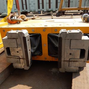
The Emergency Fall Arrest System (EFASTM) is designed to arrest and support a conveyance after a rope failure scenario by using hydraulic activated clamps, onto steel, rope, and wood shaft guides in the mine shaft.

The system can be triggered electronically or mechanically from a rope monitoring device.

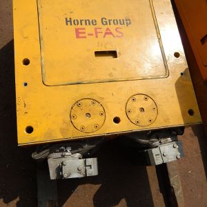
EFASTM consists of a number of clamps, a hydraulic power unit and an electronic activation and control system.

Each clamp is a self contained EFAS and functions independently, with no external hydraulic piping. Hydraulic piping is only required for chairing components, should a combined EFAS and chairing system be required. Each clamp will thus activate even if there is a problem with another clamp. The clamps are designed with a safety factor of 2 on holding capacity. This means that even if half of the clamps on an installation were to fail, the conveyance would still be arrested.

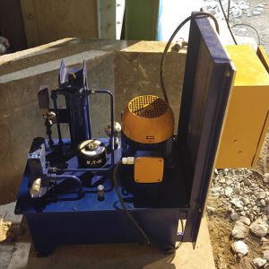
The number and capacity of the clamps used depend on the mass of the conveyance. The clamps are activated or triggered either by using a mechanical or PLC controlled activation system. The hydraulic power unit is used to charge the accumulators and is installed on the bank level.

Call us today at +1 (705) 791-8963 for more information on hoist arresting systems, mine hoist arresting systems, conveyance arresting systems, lift arresting systems, or elevator arresting systems.


Benefits


Learn how the EFASTM can benefit your mine.

Virtually eliminate the occurrence of inadvertent activation.

Safe deceleration rates with both a fully loaded cage and a single occupant.

Each clamp is a self-contained EFASTM and functions independently.

Modular System - Plug ‘n Play, Easy Maintenance

Fail-to-Safe design

Multifunctional. Can be used a both a chairing device and  safety catch

FAQ

Frequently asked questions about EFASTM

Why should I consider using EFASTM?

  • Virtually eliminate the occurrence of inadvertent activation
    • Activation decision is made on the cage
    • Activation is controlled at the source, no delays
  • Evaluated by an Independent FMECA authority
    • Equivalent to a Safety Integrity Level (SIL) 2 electronically and Mechanical Category 3
  • The system is Fail-to-Safe
    • This is very important because of the risks posed by inadvertent activation
  • Can work on steel, rail, rope and wooden guides
  • Multifunctional
    • Can be used as a chairing device as well as an EFAS™
  • Safe for even a single occupant
    • EFAS™ provides acceptable deceleration rates with a single person in the cage as well as with a full load of people.
    • Deceleration rates are adjustable to be less than that of the hoist to prevent slack rope during activation
  • Low jerk rates
    • EFAS™ jerk rates are much lower than safety dogs or wedge systems.
  • Ample redundancy
    • Each clamp is a self-contained unit with all critical parts enclosed in the clamp housing providing protection to critical parts.
    • No exposed critical hydraulic pipes.
  • Ease of maintenance
    • The system has self-diagnostic capability.
    • Maintenance is limited to swapping a faulty component with a spare one. This can be a clamp or one of the control units. The faulty unit is then returned to Horne for repair.
  • Real-time monitoring and confirmation of cage and payload mass.
  • Belling and Speech from Cage
    • The communications channel also provides speech and belling that can be added at any stage. This is very useful during shaft examination, allowing for communications throughout the entire shaft, without any dead spots or areas in the shaft.
  • No shaft obstruction
    • Nothing projects out into the shaft
  • Slack & tight rope monitoring
    • The system provides a slack rope & tight rope monitoring capability that can be set-up for different configurations.
    • This can then prevent a rope break that is caused by a slack rope condition where the conveyance is stuck in the shaft and then comes loose causing the kink in the rope to break the rope.
    • The system has warning parameters that can be set to pre-determined values.
  • Repeatable Trigger Point
    • The use of load cells to measure the actual mass, allows a repeatable pre-set trigger point. This allows for a more reliable system when compared to mechanical spring activation that can age over time and become more variable, thus minimizing the possibility of inadvertent activations.
  • Once activated, EFAS™ cannot be released accidently
    • EFAS™ can be released from the winder/hoist control room remotely or physically from the cage as dictated by a safe working procedure.


What does a Basic System look like?

A basic EFAS™ consists of the following:

  • EFAS™ Clamps
  • EFAS™ Hydraulic Power Unit
  • EFAS™ Controller
  • CCS3000 Shaft Communication System

The activation system is supplied by our communications partner Guduza Systems Technologies.The Guduza CCS3000 Shaft Communication System consists of the following components:

  • Cage PLC unit
  • Load cells in rope attachment Pin
  • Cage interface unit
  • Cage radio unit
  • Batteries

The Emergency Fall Arrest System (EFAS™) is designed to arrest and support a conveyance after a rope failure scenario by using hydraulically activated clamps acting on steel, wooden, or rope guides in the mine shaft.

EFAS™ consists of multiple clamps, a hydraulic power unit and an electronic activation and control system.

The EFAS™ is designed to support the maximum static mass of the conveyance and payload.

EFAS™ Clamps

Each EFAS™ clamp is designed to function as a stand-alone system with all parts being installed inside the clamp housing. The number and capacity of the clamps used depends on the mass of the conveyance.

Each EFAS™ Clamp has an accumulator and cylinder enclosed in the housing.

Each EFAS™ clamp is designed to hold more than twice the rated holding capacity. E.g. A 5 ton EFAS™ clamp will hold up to 10 ton. This means that up to half of the EFAS™ clamps can fail and the system will still stop the conveyance.

(This is unlikely as the clamps would indicate any maintenance issues and are checked regularly in the recommended maintenance schedule.)

The accumulator in each clamp is monitored and controlled with appropriately fitted pressure transmitters and screw in cartridge valves respectively.

Whether each clamp is open or closed is monitored by a magnetic proximity switch.

EFAS™ Hydraulic Power Unit

A hydraulic power unit (HPU) is used to recharge the accumulators and is installed on the bank level. Only one HPU is needed per shaft.

EFAS™ Control System

The clamps are activated or triggered either by using a mechanical or PLC controlled activation system. The system can be triggered electronically or mechanically from a rope monitoring device.

The system is activated when the rope end load as measured at the rope attachment indicates a slack rope or a rope failure. The cage PLC will then activate the activation valve in the clamp that will allow oil to flow from the accumulator to the clamp cylinder causing the arms and shoes to grip onto the shaft guides, arresting the cage.

What factor of safety is used on the clamps?

All the clamp units are designed with a minimum safety factor of 5 on ultimate tensile strength. On clamping force, a safety factor of 2 is used.

How is the system activated?

The system will only activate under the following two conditions, it will not activate inadvertently as a result of any other conditions. The system will work as designed even if the hoist safety circuit has been compromised or bridged out, because all activation decisions are made on the cage.

Slack rope:

The system will only activate if the rope end load is less than the minimum set value, usually 20% of empty cage mass. The hoist will be tripped immediately.

Rope failure:

This is a very low risk situation, as the EFAS virtually eliminates all the causes of rope failure. The system will activate because the rope end load will be less than the set activation value, and as there will be a loss of the communication heart beat signal.

If for any reason the rope load does not reduce below the set value the system will activate on loss of the communication signal.

The hoist will be tripped immediately as well.

Does the System Fail to Safe?

The Communications system provides for a number of safety circuit outputs that will fail to safe if triggered.

  • Signal fail dry contacts
  • Slack rope fail dry contacts
  • Tight rope fail dry contacts
  • Communications heart beat dry contacts
  • Processor heart beat dry contract
  • System (Regulator & Bus fail) dry contacts Should any of these components have the potential to fail, the system will fail to safe and stop the hoist in one of two modes:
  • Trip Winder
  • Trip end of wind These will activate a controlled stop preventing damage to equipment or injury to people. In terms of Failsafe operation of the mechanical system, there are two conditions under which the system must “fail to safe”
  • The first is under normal hoisting operations the clamps must not apply when it is not needed as this will cause inadvertent activation. This is an unacceptable situation and must be avoided at all cost.
  • The second is that after activation, it must stay in situ (place) until the rescue has been affected The mechanical system achieves both conditions using a combination of hydraulically applied spring released clamps and a hydraulic system equipped with enough redundancy to hold pressure once the clamps are applied.


Redundancy:


On the clamps

The clamps are actuated hydraulically and are equipped with stainless steel springs that will hold them open. The reason for this is that we need to guarantee, that the clamps will not apply and remain open during normal hoisting duty.


The modular clamps are designed to hold twice their rated holding capacity. Thus a 6 ton (13 440 lb.) clamp will hold 12 ton (26 880 lb.). Each clamp is a self-contained fully functional EFAS unit designed in such a manner that on a two clamp system, each clamp on its own is able to arrest the conveyance in a safe manner. On a two clamp system we can lose one clamp and still hold the complete cage safely.


To release the system it is important to ensure that it cannot be released accidently. For that reason there is a complete separate release circuit.


On the hydraulic system


Accumulators are double the needed size to allow for issues like air in the system, and temperature fluctuations.


If by accident pressure is lost in one clamp on a 2 clamp system, the other clamp is capable of holding the complete weight of the conveyance.


Furthermore each cylinder in the clamps has been equipped with a pilot operated check valve. This will allow hydraulic oil in to the cylinder to activate the clamp but will not release any pressure from the cylinder. These are zero leakage valves.


The advantage of this is that if we lose hydraulic pressure in any one of the clamp systems and all the pressure from one accumulator is lost, the clamps will not release. If there is a leak in one of the clamp cylinder the other one will remain clamped.


Each accumulator is interlocked using a pressure switch, so that if there is a leak during normal operation and the accumulator pressure drops, then maintenance personnel will be alerted.


Communication system


The surface panel has a number of safety circuit relay outputs. If any of the outputs don’t work for whatever reason the conveyance side is self-contained meaning it doesn’t require the surface side to function. The winder should be “tripped” out because of this, causing the system to fail safe in a preventative manner.


The system will only loose its transparency (signals to hoist) but not functionality.

Will system activate inadvertently?

Inadvertent Activation

With EFAS it is possible to virtually eliminate the occurrence of one of the most significant safety risks to transporting men in cages. Inadvertent activation of safety catch systems generally happens when the hoist stops during an emergency situation. The Horne EFAS will know that this is a hoist emergency stop and not a rope failure, and therefore not activate.

Slack & Tight Rope Monitoring:

As slack rope conditions are the most dangerous, some hoist controls use a trip wire at the hoisting drum to detect a slack rope condition. This control only works as long as the conveyance is around the collar area.

As the conveyance descends in the shaft, a point will be reached where the rope is kept tight due to the weight of the rope alone. Then this function will no longer be feasible as a safety function.

The communications System provides a slack rope monitoring function that will monitor the slack rope condition throughout the entire shaft and not just at the collar area. Warning points can be set to warn if this condition starts to occur, providing preventive action before the hoist is tripped.

During a slack rope condition the EFA system will stop the hoist before any damage can occur to the rope by not allowing the hoist to pail out rope on top of the cage thus preventing the rope from kinking.

Are Deceleration Rates Safe?

With EFAS the deceleration rates can be adjusted not to exceed the deceleration rates of the hoist. Therefore it will not cause a slack rope condition that can lead to the kinking of the rope.

Deceleration rates can also be adjusted to meet or improve on currently liberal G-Force deceleration criteria set in most Mining Jurisdictions globally. A great improvement to health and safety standards currently set in most mining jurisdictions.

What about Maintenance?

The mine must do a weekly maintenance inspection and test of the EFAS on both the mechanical and communication system as prescribed in the maintenance manuals. This will take approximately 10 minutes.

This includes a full clamping pressure check on surface level. The designed pressure must be reached for 5 minutes.

One set of batteries must be kept on charge. The Batteries has to be changed approximately every two weeks.

The clamps need to be refurbished every two years and/or immediately after an EFAS activation.

E-FAS® Test Videos

See the E-FAS® system in action!

Request More Information

For more information on the E-FAS®, please fill out the form below.